The module system
Six slots, a printed shell, M2 screws, and a JST cable per input. Everything else about a module is up to whoever designs it.
A module is a printed part 3 x 6 cm that drops into a slot and screws down with M2 screws into heat-set inserts. Whatever switch, encoder, button or lever sits in it wires back to the board through a JST 1.25mm cable per input, so a module with two switches uses two of them. There is no bus, no addressing, and no per-module electronics. The board just sees switches closing to ground.
That is the reason a module swap takes five minutes and the reason designing a new one is realistic. You are not writing firmware for it. You are printing a shell that holds a part and running two wires.
- Slot size
- 3 x 6 cm
- Slots per box
- 6
- Fixing
- M2 screws into heat-set inserts
- Wiring
- JST 1.25mm, 2 pin, one cable per input
- Standard hole
- 12mm, with adapters for 6mm and 7mm
Orientation
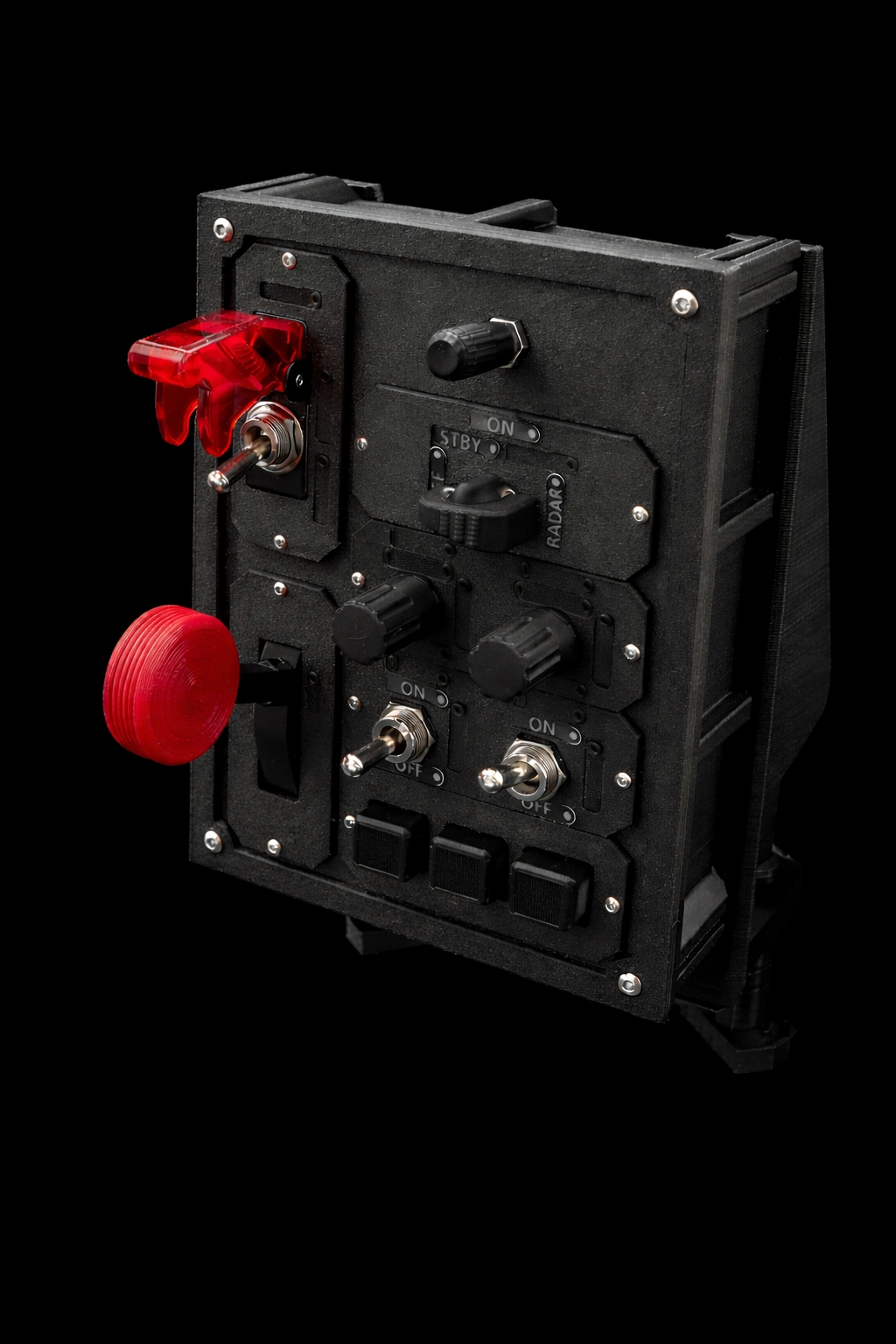
Slots are 1:2, so depending on the layout and rotation a slot sits either vertically or horizontally. Most modules fit either way. Two do not: the lever needs the taller clearance to travel, and the guarded switch needs room for its flip cover, so both are vertical only.
A module can also span more than one slot. The two-slot rotary switch does exactly that, taking two adjacent slots to fit an 8-position sweep and its labels.
Labels
Labels are separate printed parts, and all of them are backlit except the key module's. How many a module has depends on what it does: one per position on a rotary, one at the top plus one per position on the guarded switch, four per position on the dual-position module, and none at all on the lever. The labels page covers printing them.
The dual-position module is the blank canvas
Before you design a new module from scratch, check whether the dual-position module already does it. It is two threaded 12mm holes with adapters for 6mm and 7mm parts, and it takes any switch, encoder, button or other. If you need a different size, change the perimeters in CAD.
Designing your own
Fork the Onshape document, keep the outer shape and the screw positions, and put whatever you want inside. The firmware needs no changes for a plain switch or button. Something with a quadrature output needs an ENCODER rule, and anything with a middle position needs a NOR rule, both covered on the firmware page.
This is the part of the project I am hoping for most. If you are building a module and get stuck, ask on the Discord and I will happily help you get it working.