Assembling the enclosure
Four steps and the box is closed. This is the short chapter.
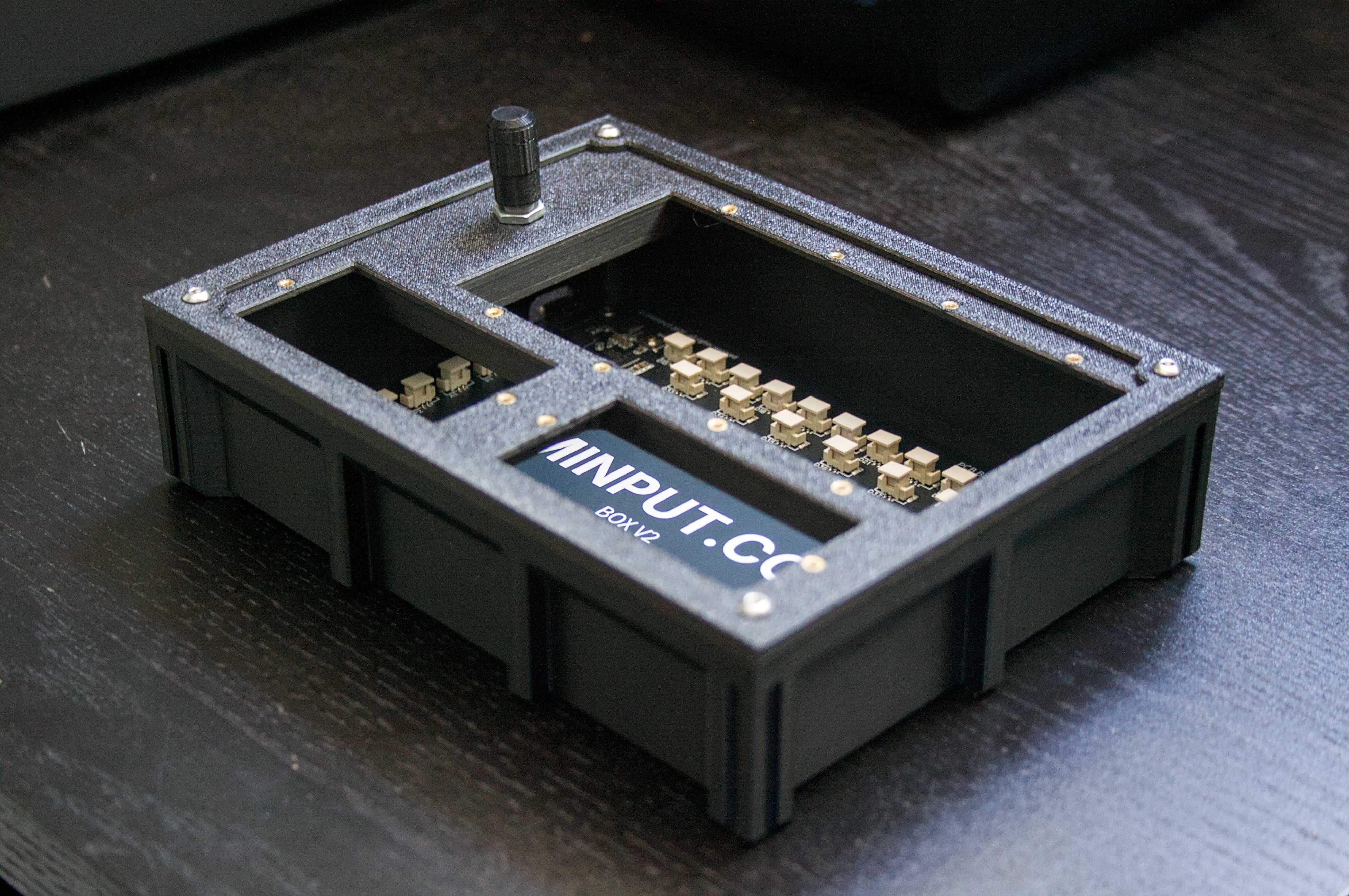
Lay these out first
- Printed box and plate
- Printed plate cover
- Main PCB with its washers
- Your built and soldered modules
- 16 x M2x4mm screws for the modules
- 8 x M3 screws, 6-12mm for the front four
- M2x2 and M3x6 heat-set inserts, one per screw
Tools
- Soldering iron
- Hex keys for the M2 and M3 screws
Putting it together
- Apply the inserts to the box and plate.
Low heat and gentle pressure helps a lot. This is the one step you cannot undo cleanly, so take the extra minute per insert.
- Screw in the PCB and don't forget the washers.
- Put the plate cover around the plate.
It requires some persuasion. A tight fit here is the correct fit.
- Screw your modules in, plug in the connectors, and screw on the plate.
Rotary encoders only work on the direct GPIO pins, D1 to D22. Everything else can go on any connector, but an encoder plugged in elsewhere will not respond. If you have a rev1 board, contact me for some direct help instead.
Test every input before that last plate goes on. Getting back to a loose connector afterwards means taking it all off again. Plug the box in and flip each control while watching the live monitor in the desktop app.