Building the modules
Build only the modules you ordered. Each one is self contained, so you can do them in any order and stop whenever you like.
Every module is a printed shell 3 x 6 cm that holds a switch, encoder, button, or lever. Three of them go together in a couple of minutes. The lever is the one that takes real work, so leave it for when you are warmed up.
Soldering is covered in the next chapter, but decide the order per module now. On the dual-position, rotary, and guarded switch modules it is way easier to solder the switch before mounting it. The key module is the opposite: there you really do have to build first, then solder. The lever can go either way; I suggest building it first, but it is not required.
Dual-Position Module
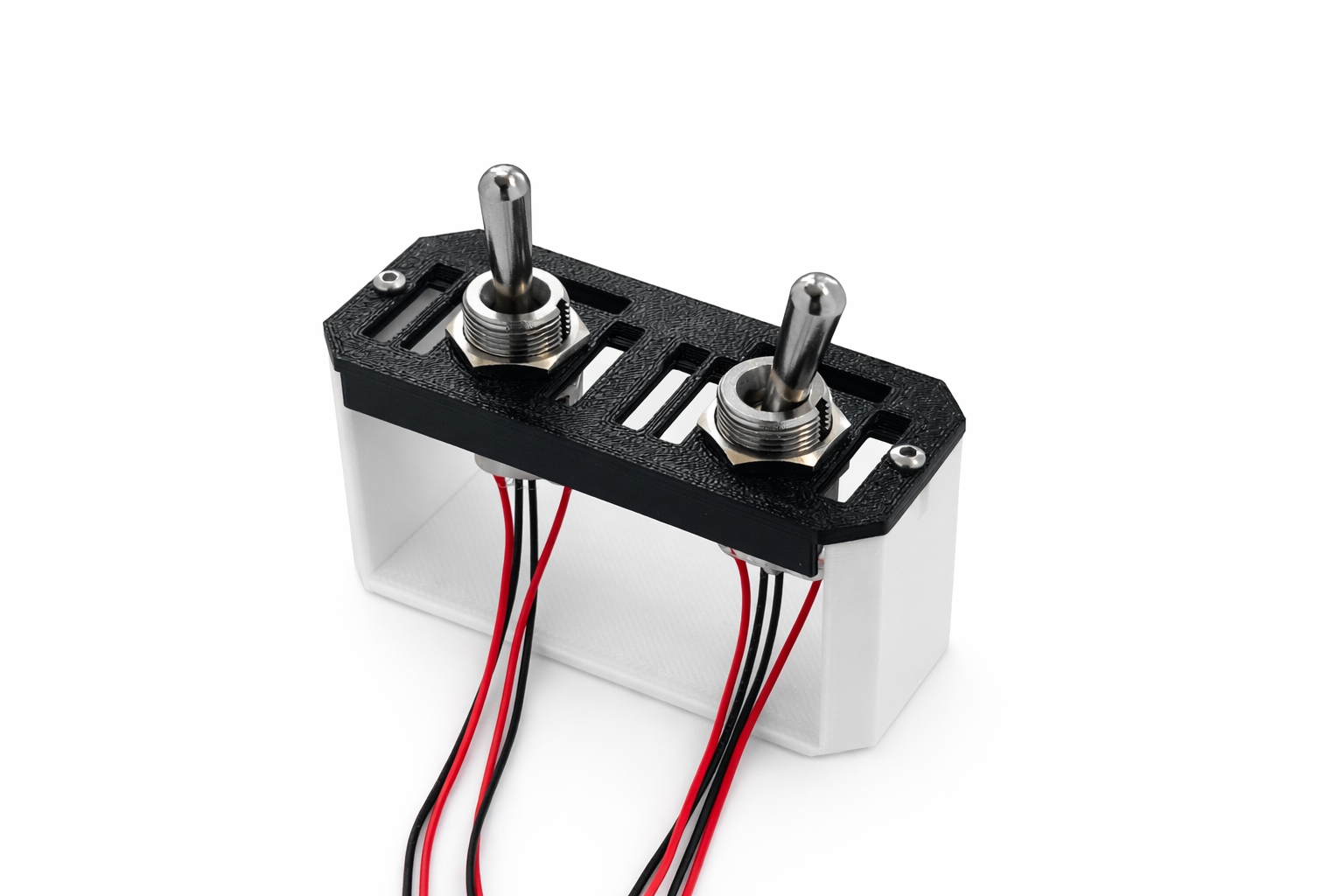
A module with two threaded holes for any switch, encoder, button or other. No particular parts are required, use anything you wish.
The holes are 12mm, with threaded adapters for common sizes (6mm and 7mm). Screw the adapter into the hole first if your part is smaller, then mount the part into the adapter. The adapters can be really difficult to get in on this module, but they do go; keep at it. If you need a different size, change the perimeters in CAD, or ask me on Discord.
Rotary Module
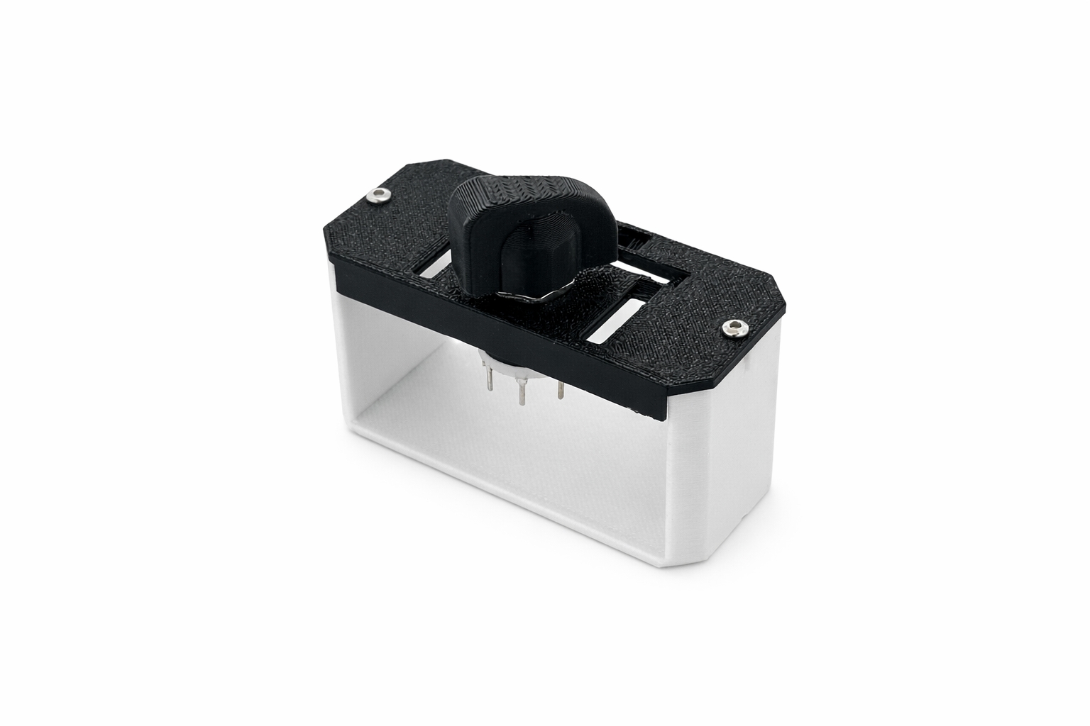
A module with a single hole and labels around it, to be used with a generic 8-way rotary switch. Includes a custom knob. The fit on the shaft has to be quite precise, so if you print your own you might have to scale it up or down slightly.
The switch is the same 8-way part the store sells this module with, and only the first five positions of its sweep get wired. That is why it is sold as a five-position rotary while the shopping list says 8-way.
Lay these out first
- Printed housing
- Printed knob
- Small 8-way rotary switch
- Mount the rotary switch into the hole and tighten its nut.
- Push the printed knob onto the shaft.
The knob should clear the face of the module and turn without catching on it.
Two-Slot Rotary Switch Module
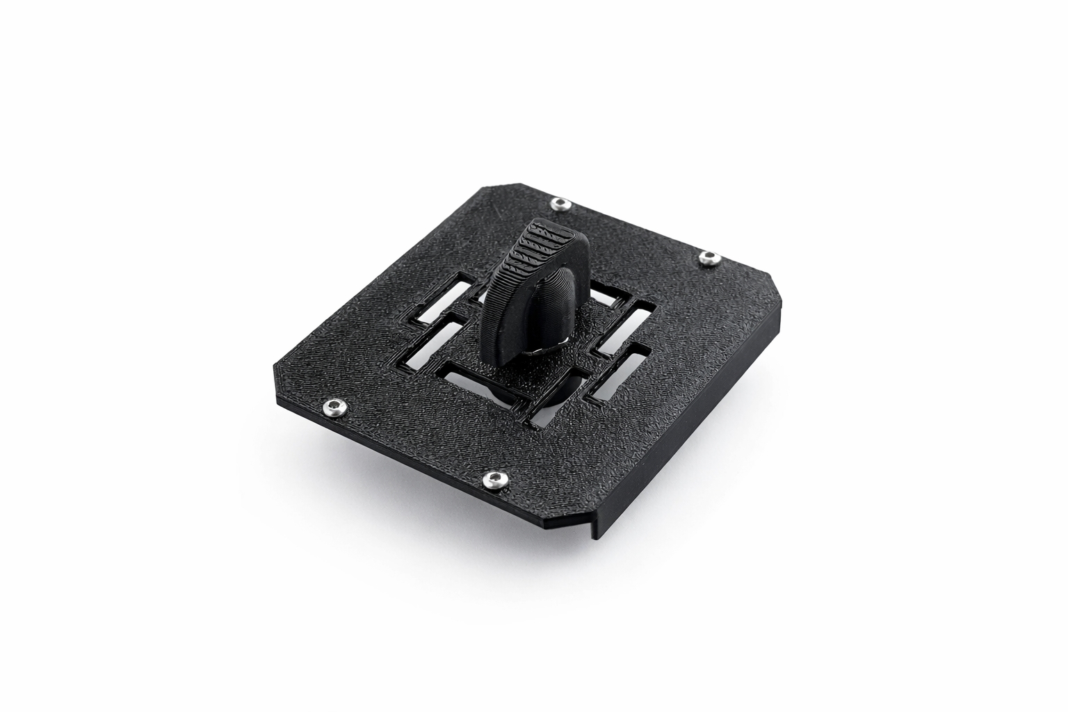
The same rotary switch on a wider face. This module spans two adjacent slots, which leaves room for the full eight-position sweep with a label at every position. In the configurator it fills both slots at once.
Lay these out first
- Printed housing, two slots wide
- Printed knob
- Small 8-way rotary switch
Assembly is the same as the single-slot rotary above: mount the switch in the hole, tighten its nut, and push the knob onto the shaft. The difference comes later, in soldering and wiring, where all eight positions get read instead of the first five.
Key module
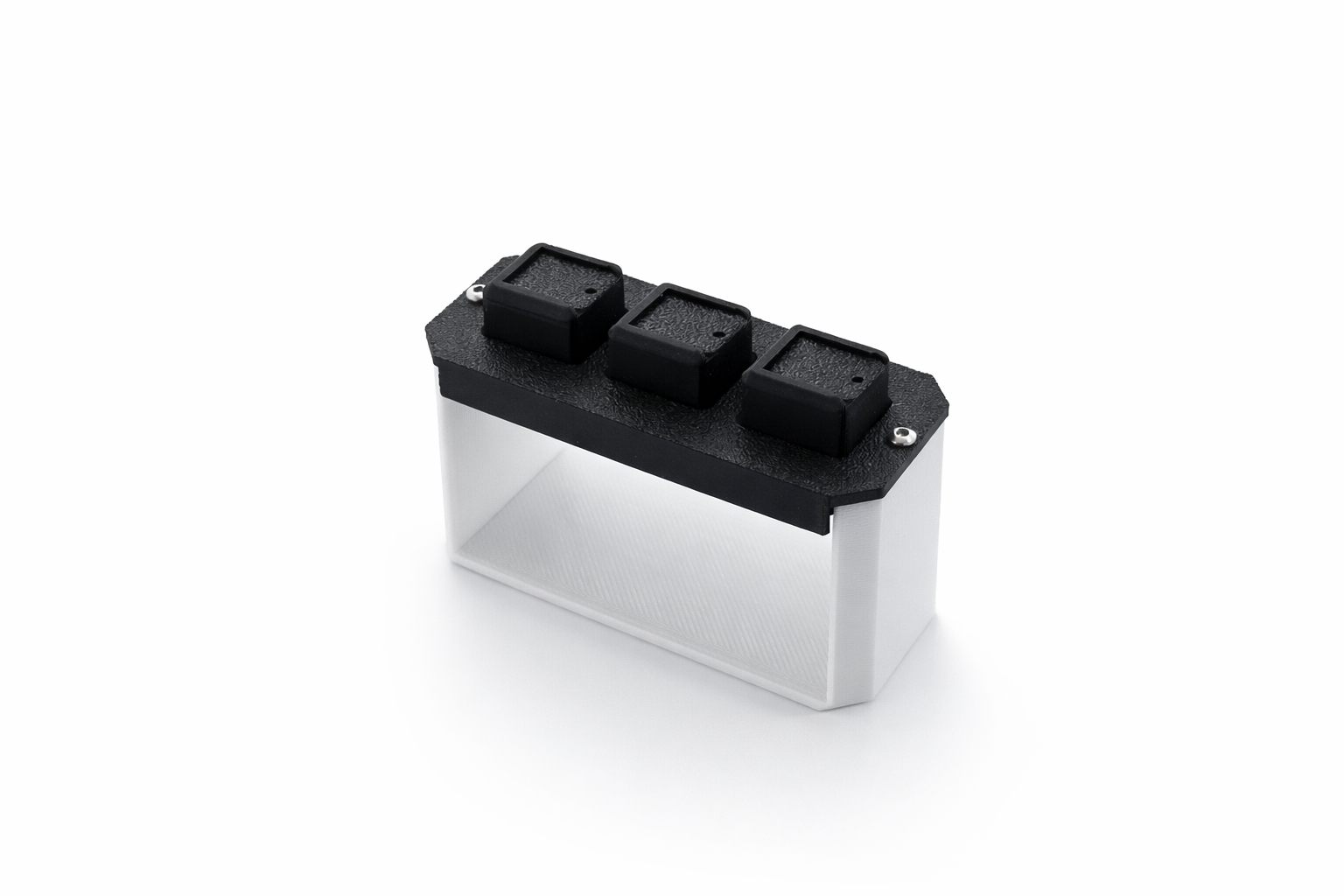
Designed around super cheap 8*8mm keys, this module has three super smooth square buttons with labels (not backlit). Build all three keys the same way, one after another.
Lay these out first
- Printed main part
- 3 printed key-caps
- 3 x 8x8mm keys
Tools
- Hot glue
- Lubricant (optional)
- Press-fit the linear key to the key-cap.
- Apply hot-glue to the bottom of the housing in between the two holes for the pins.
- While the key is fitted to the key-cap, insert it in the main part and press down.
Keep all three keys in the same orientation. It makes it far easier to know what pins to solder once they are all seated and you can no longer see which way round they went in.
- Repeat for the other two keys.
Lever module (gear or hook)
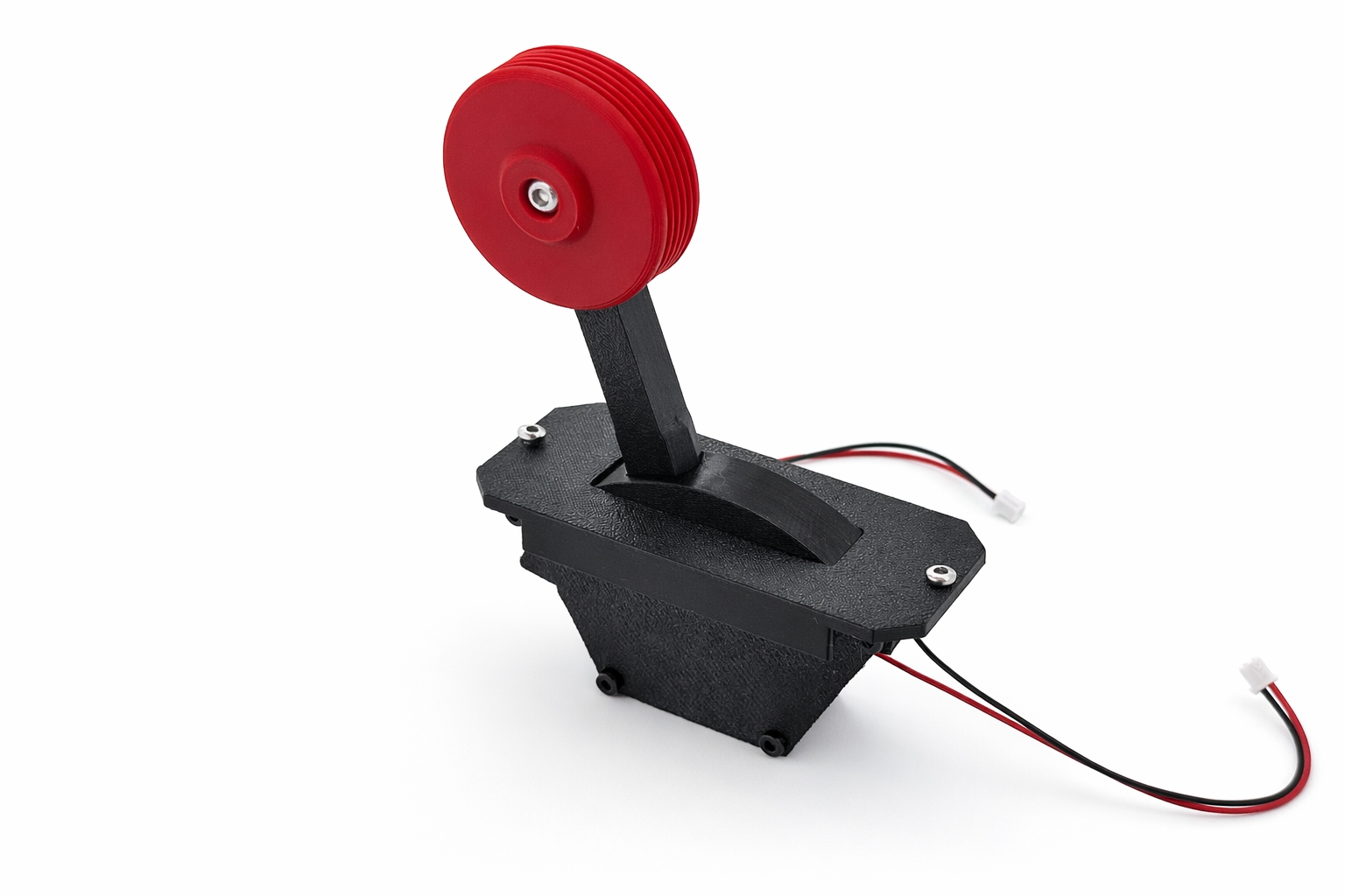
A compact mechanical push-pull lever with gear or hook knob. Making use of standard 12.8*7.3mm micro switches. This is the longest module to build, and the only one where the order of operations matters.
Lay these out first
- Printed housing, pivot, lever, and action plate
- Printed gear or hook knob
- 5x6 ball spring
- 2 x micro-switch with minimum 11mm handle
- M3 screw (6-8mm length) and M3x6 insert
- 4 x M2 screw (6-9mm length) and 4 x M2x2 inserts
Tools
- Soldering iron for the inserts
- Hot glue
- Any lubricant
- Apply the inserts. One per screw, so five in total.
- Apply lubricant to the rod and put it in the pivot.
- Press fit the ball spring into the hole on the lever.
This might require a lot of force. That is expected, and it is the one place on this module where you should push hard.
- Put the pivot with rod in the housing.
Don't use too much force here. Unlike the ball spring, this part goes in gently.
- Apply lubricant to the lever action plate and screw it on.
The lever should now move through its travel and hold at the top.
- Glue the micro switches in place. Check the orientation against the photos on the lever module post before the glue sets.
- Screw the knob on.
Guarded switch module
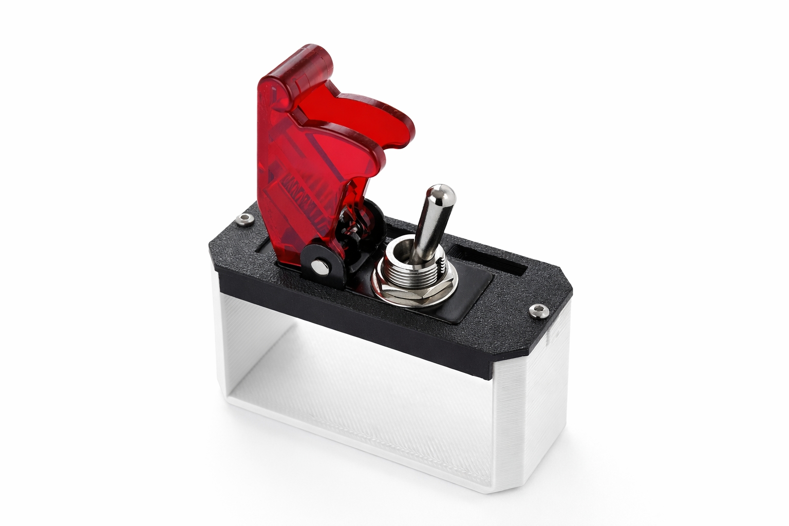
A module for a guarded switch. Any guard cover similar to this one including a switch or this loose cover will work.
Lay these out first
- Printed housing
- Guard cover, with or without its own switch
Mount the switch through the housing and tighten its nut, then fit the cover over it.
Cover Module
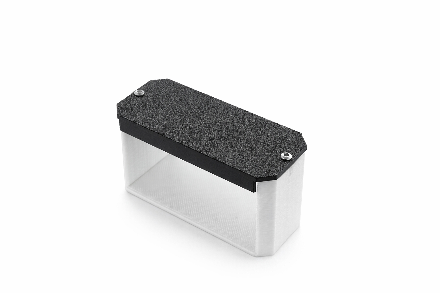
A flat printed cover for any slot you do not want a control in. Nothing to build and nothing to wire.